Well, this is another issue in “just let me add this quickly so I can test what I wanted to do originally”. What I started with was adding a Depth of Field shader to the post processing layer of my OpenGL renderer, what I ended up with was thinking a lot about model unit scale and environment maps. Let me explain…
One goal I have for the modeling core is to make it intuitive for non 3D-artists. As a consequence, the camera model is based on focal length, aperture width and so forth. But for all of this to work, there has to be a relation between the OpenGL coordinate system and the real world. This is what the model unit does. It defines how many meter a single unit of the model coordinate system is. Some formats like COLLADA allow to specify the model unit inside the file, for others you have to know the convention under which the original creator worked on.
Reading the Model Unit
This is where the first problem arose: As great as the assimp import library is, it does not provide the model unit even if it is contained in the file imported. So what I ended up doing is at least for COLLADA parse it myself. This was done rather quickly as I had the BOOST library integrated anyway and use it for XML parsing:
if ( boost::filesystem::path(filePath).extension() == ".dae" )
{
    boost::property_tree::ptree pt;
    boost::property_tree::read_xml(filePath, pt);
    float const modelUnitInMeter = pt.get<float>("COLLADA.asset.unit.<xmlattr>.meter", 1.0);
    scene->setModelUnit(modelUnitInMeter);
}
Environment Maps
Next up, I needed some form of background to really see how the depth of field affects the total composition. So I added support for “surroundings”, basically a scene file that can be attached to the opened scene. Everything in the surrounding cannot be edited and does not affect the majority of computations. It’s just there to be rendered…
The easiest type of surrounding is a sphere mapped with an environment texture to it. Good, free environment textures are hard to find, but there are some at Open Footage. Env maps are often HDR images to support image based lighting, but luckily the image library I use (FreeImage) has tone mapping operations to map an HDR to a normal, low range image.
Ground Plane
Once the env map can be loaded, the question is what geometry to map it to. The easiest choice is to use a UV sphere, flip the triangle order and normals and invert the U-direction of all texture cordinates (since we want to view the sphere from inside). However, this makes your object hover in mid air as their is no ground. Which led me to quite an interesting sub problem:
Can we use a spherical env map and extract a ground texture from it?
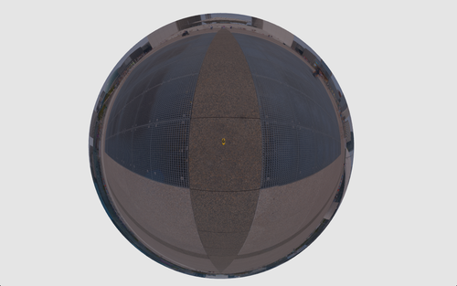
The problem is that a spherical map has quite a bit of distortion and simply flattening the bottom half of a sphere leads to something like this (note the yellow blob in the middle which is actually the car model):

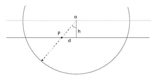
After some scribbling and scratching my head, I found the solution to be:
0.5 - atan2(cameraHeight, mesh->getPosition(vertex3).norm()) / M_PI)
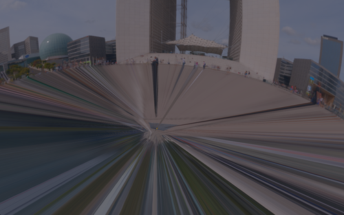
What this does is assume the sphere texture has been recorded at some height, let’s say 1.80m. Based on the distance from the center, each vertex of the ground plane is projected on to a sphere that is at camera height ABOVE our ground plane. This leads to something like this:

Which brings me back to the beginning, the model unit. The above result may look weird, but it is actually correct! The thing is that the geometry has been generated with a radius of 500m (the model itself is roughly 5m). If the recording camera was at 1.8m height, at 1.8m along the plane, it samples the part of the texture that is 45 degrees from the bottom. After that, less and less pixel of information are available per meter as we travel along towards the border of the ground plane.
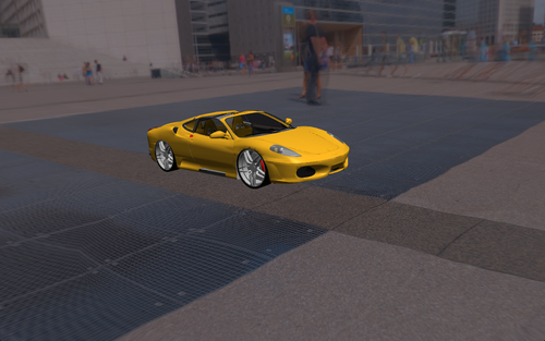
The following shows what the ground looks like when being close to the model (the center of the ground plane):

That’s actually not that bad for an input texture of 2048×1024! You might have noticed a slight “wobbling” along the grids. This is actually due to fact that we try to map a sphere texture to a plane. Here is what the mesh looks like:
The wobbling actually occurs along the diagonal of each quad and is due to the linear interpolation along the triangle edge. That’s OpenGL for you, there’s not much one can do about this except increasing the vertex count.
Edge Alignment
I tried to change to a regular grid of quads as ground mesh but on the one hand that’s more complicated to code if one wants the semi sphere to connect to it perfectly. Also it produces even worse results, as the edges are worse aligned compared to the vertical direction of the spherical texture!
So I finally ended up flattening the bottom half of a UV sphere and then contracting the vertices towards the center such that the triangle density is higher close to the model. Note that the above screenshot also shows what happens if you don’t respect the model unit. Although the texture distortion is correct, it looks completely weird because the car itself is totally out of proportion. In fact, the distortion here is exactly the same as in the close ups above! Realizing this was a problem of model unit and not of the distortion itself did cost me a couple of hours… way more than figuring out the distortion or writing the mesh generation code!
Next up: Working on the depth of field shader. And using the environment not only as background but also as reflection in the metal paint job of the car…
Update – 7/9/2014
I finally figured out why the grate region in the reconstructed ground plane still looked trapezoid after removing the spherical distortion: After using Google Street View, I noticed that the ground at the Place de la Defense actually goes downhill. So the assumption in the equation above is slightly off, contracting the texture where the real ground goes down and pulling it apart where the real ground goes up.
So there is more to ground plane reconstruction than I though, but well, for my experiments the texture reconstructed above works fine enough…


Leave a Reply