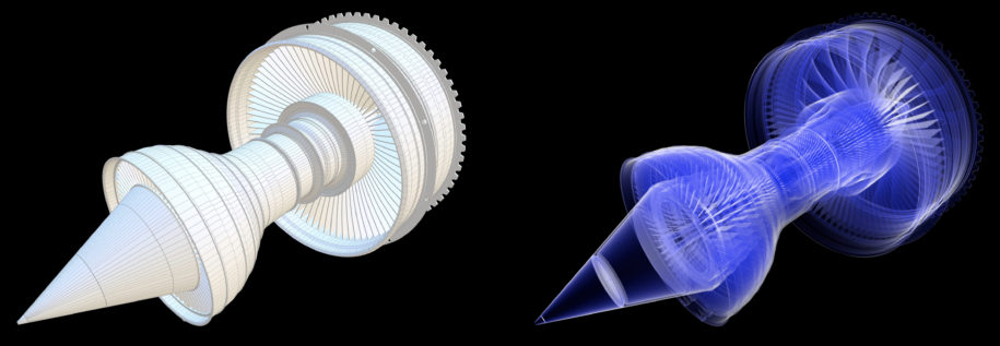
While fake x-ray shaders are not very practical, they do look nice and are easy to implement. I did neither find a nice one I liked nor a good explanation, so here goes:
The vertex program simple computes the screenspace position of the vertex by multiplying with the model-view-projection matrix. In addition, it transforms the vertex and normal into view space as input for the fragment program. Note that the normal is multiplied with the inverse transpose of the model-view matrix but using the model-view matrix directly does not produce correct results for transformations with non-uniform scaling.
#include <metal_stdlib>
using namespace metal;

struct TransformationUniforms
{
     float4x4 MVP;
     float4x4 MV;
     float4x4 MV_inverse_transposed;
};

struct MaterialUniforms
{
    packed_float4 tint;
    float falloff;
};

struct VertexInput
{
    packed_float3 position;
    packed_float3 normal;
};

vertex VertexOutput VertexShader(const device VertexInput * vertexData [[buffer(0)]], constant TransformationUniforms &transformation [[buffer(1)]], uint vid [[vertex_id]])
{
    VertexOutput output;
    VertexInput vData = vertexData[vid];
    output.position = transformation.MVP * float4(vData.position, 1);
    output.position_viewspace = (transformation.MV * float4(vData.position, 1)).xyz;
    output.normal_viewspace = (transformation.MV_inverse_transposed * float4(vData.normal, 0.0)).xyz;
    output.normal_viewspace = float3(0.0, 0.0, 0.0);
    return output;
}

fragment float4 FragmentShader(VertexOutput in [[stage_in]], constant MaterialUniforms &material [[buffer(0)]])
{
    float opacity = dot(normalize(in.normal_viewspace), normalize(-in.position_viewspace));
    opacity = abs(opacity);
    opacity = 1.0 - pow(opacity, material.falloff);
    float4 result = opacity * mix(material.diffuseColor, float4(1.0, 1.0, 1.0, 1.0), clamp(2.0 * opacity, 0.0, 1.0));
    return float4(result.r, result.g, result.b, opacity);
}
The fragment shader calculates the normalized vector from the view-space position to the eye (=origin), which is just a negation, and then calculates the absolute dot product with the normal. So if the normal is aligned with the eye-vector, it is 1, and if perpendicular, it is 0. Since an x-ray shader renders the silhouette opaque and middle transparent, the interpretation is flipped by using one minus the previously calculated value. This value is then used as the alpha value of the output color (in the example, it’s multiplied with the RGB-components as well because the Shapeflow pipeline works with pre-multiplied alpha; if yours doesn’t, use raw RGB values).
The result is improved by two optional steps:
- a falloff value between zero and one (0.3 worked well for me) “compresses” the opaque area towards the silhouette.
- the tint color is mixed with pure white depending on the opacity value such that the silhouette is white (gives the rough impression of glowing). Note the factor of two inside the clamp which causes the white part to be a bit fatter.
Nothing too sophisticated. Hope it helps…

Leave a Reply